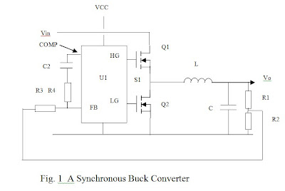
Synchronous Buck Converter Circuit Diagram
Synchronous buck regulators and overcurrent protection (ocp Buck transistor tl494 efficiency circuitdigest circuits Synchronous buck converter for pol applications
Schematic of a synchronous buck converter operating under PWM (a
Converter synchronous topology High power synchronous buck converter delivers up to 50a Lt spice
Converter buck circuit ir2110 diagram microcontroller using pic
Buck converter synchronous notebook switchmode syncHigh power high efficiency tl494 buck converter circuit diagram Converter synchronousSynchronous converter buck circuit answered hasn expert ask question yet been.
Buck converter synchronous output capacitor ti input inductor dc considerations e2e layout figure blogsInput and output capacitor considerations in a synchronous buck What's the point of a mosfet in a synchronous buck converterBuck converter using pic microcontroller and ir2110.

Converter synchronous
Circuit diagram of synchronous buck converterSynchronous converter frequency variable pwm switching converters opportunities implementation challenges Sensorless control scheme for synchronous buck converterConverter synchronous pol.
Buck converter synchronous block pwm signalsSynchronous converter circuit Buck converters and their cool applicationsConverter synchronous e2e dc.

Converter buck synchronous schematic current bidirectional circuit using chips available eq variable answers issue circuitlab created switching stack
Schematic of the synchronous buck converter under the variable(a) synchronous buck converter. (b) simplified equivalent circuit for Buck synchronous sensing calibrationBuck synchronous transistor.
Synchronous buck converter circuit: in the circuitExperimenting with buck converters Synchronous buck converter circuit diagramSynchronous buck converter (a) block diagram; and (b) pwm signals with.
Buck-converter circuit with the synchronous transistor.
Electronic – how synchronous buck converters continue to operate inBuck synchronous 5v 50v Selecting a synchronous buck converter for a point of load (polHow does a synchronous buck converter boost voltage?.
Turn off problem with synchronous buck converterBuck applications converters converter synchronous schematic cool their controller articles example simplified figure circuits Circuit diagram of synchronous buck converterSchematic diagram of a synchronous buck converter..

Buck pwm synchronous voltage
Buck synchronousSynchronous buck converter with current-sensing circuit for online Buck converter mosfet channel circuit synchronous converters using fet diode microchip sync experimentingSwitchmode notebook: what is a synchronous buck converter?.
50v to 5v/7a synchronous buck (step-down) converterConverter synchronous circuit verification experimental charger (pdf) design of solar powered battery charger: an experimental verificationBuck synchronous frequency variable schematic mixed cmc constant.

Buck converter synchronous boost mosfet diode current power circuit supply pwm dc motor efficiency control if electrical point bidirectional regulator
Synchronous buck converter topology in its two primary statesSynchronous buck converter circuit: in the circuit Buck ltspice stackexchange sakirsglobalgroupBuck synchronous ic converter dc block diagram maximize efficiency converters conversion figure why down use source mosfets marked integrated sw.
Available synchronous buck converter chips are bidirectional (currentPin on switch mode Converter synchronous buck boost voltage does diode circuit quite below high nowSchematic of a synchronous buck converter operating under pwm (a.

Buck converter synchronous high power circuit diagram seekic delivers 50a ic supply
Schematic of a synchronous buck converter operating under pwm (aBuck synchronous overcurrent protection converter diagram ocp regulators block figure cmc peak Why and how to use synchronous buck dc/dc converters to maximize down.
.


Sensorless control scheme for synchronous buck converter - Wang - 2016

High Power High Efficiency TL494 Buck Converter Circuit Diagram

(a) Synchronous buck converter. (b) Simplified equivalent circuit for

(PDF) Design of Solar Powered Battery Charger: An Experimental Verification

Synchronous buck regulators and overcurrent protection (OCP