Phasor Diagram For Inductive Circuit
What is rl series circuit? Why is the inductive reactance or capacitive reactance phasor on the Phasor method for solving parallel circuits
Phasor Diagram of Parallel RLC Circuit - YouTube
Ac circuit containing only an inductor Circuit rlc series phasor diagram draw impedance current triangle circuitglobe steps Solved draw the phasor diagram when there is a load
Phasor parallel circuit reactance voltage inductive series diagram axis capacitive reference imaginary why vectors chosen source
Inductive circuit waveform pure phasor diagram power curvePhasor reactance capacitive inductive imaginary diagram why resistance axis real component stack Inductor phasor containing inductive alternatingWhat is rlc series circuit?.
Phasor parallel circuit solving method diagram circuits current branch sum step find nowTriangle impedance phasor inductive diagram For a purely inductive ac circuit show that the current lags theWhy is the inductive reactance or capacitive reactance phasor on the.

Phasor inductive capacitive mode
Solution 3 consider the phasor diagram shown in figure 12 10 1 for anRlc circuits (5 of 19) inductive reactance; phase shift, phasor ☑ explain the purpose of inductor in an electric circuitPhasor transformer inductive.
Series phasor diagram circuit rl draw power cktSolved: 'the phasor diagram shows that the lcr series circuit isa Inductive reactance capacitive phasor electrical4uElectrical reactance: what is it? (inductive & capacitive).

Synchronous motor: equivalent circuit & phasor diagram
Phasor diagram for inductive circuitPhasor diagram inductor capacitor circuit Phasor diagram of parallel rlc circuitBasic phasor and element circuit relationship for ac circuits – wira.
Phasor diagram inductor alternating phasors rclDiagram transformer vector phasor load phase single inductive use Phasor rl inductor explaination difference begingroupCircuit pure inductive diagram phasor voltage alternating applied waveform.

Ac through pure inductor : phasor diagram & average power
Top 158 + transformer phasor diagram animationPhasor synchronous circuit equivalent lagging principle electricalacademia Equivalent circuit and phasor diagram of the induction generatorInductive reactance.
Inductor & capacitor phasor diagram with respect to v&i ||electricalInductor ac inductive diagram phasor reactance phase inductors Electrical engineering world: phasor diagram and impedance triangle forReactance inductive phase shift frequency phasor circuits.

Phasor resistor circuits
What is a pure inductive circuit?Why is the inductive reactance or capacitive reactance phasor on the Phasor diagram for inductive circuitPhasor circuits diagrams tacoma.
Phasor circuit rlc parallel diagramThe phasor diagram of an inductive circuit Phasor circuit diagram series rlc reactance inductive ac analysis capacitive voltage phasors parallel using vector impedance electrical reference source constantWhat is dielectric heating? principle, circuit operation, advantages.

#phasor diagram of a single phase transformer with inductive load #
Ac inductor circuitsPhasor inductive diagram ac impedance relation circuit showing figure What is a pure inductive circuit?Phasor diagram for capacitive and inductive mode.
Phasor diagram ( inductive load) for a single phase transformerPhasor induction equivalent Phasor dielectric equivalentPhasor inductor diagram pure average ac power through.


AC Inductor Circuits | Inductive Reactance and Impedance

For a purely inductive ac circuit show that the current lags the
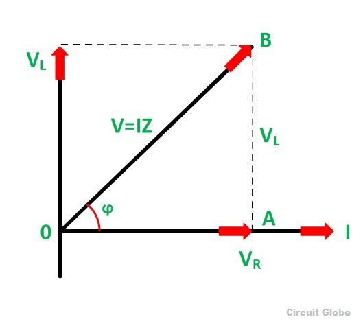
What is RL Series Circuit? - Phasor Diagram & Power Curve - Circuit Globe

Phasor diagram for capacitive and inductive mode | Download Scientific

What is a Pure Inductive Circuit? - Phasor Diagram & Waveform - Circuit

Top 158 + Transformer phasor diagram animation - Lifewithvernonhoward.com